Work Day
Date: 2.20.19
Time: 10:00 AM-2:00 PM
Location: Logan HS
Goal: Test charging system and BlueTooth connection
Students:
Some work was done leading up to this meeting on Monday, 2.18.19. Alex worked worked on resoldering some electrical connections on the battery charging circuit. We were not getting any output when we bench tested it with a voltage. Some troubleshooting found a loose solder connection that was corrected and the circuit worked. Again when we are working with surface mount components the scale is much smaller and we seem to have more soldering faults.
Also, the new spring was mounted on the heel linkage and the new motor an pinion gear were installed with 3 ft. wire leads soldered and shrink warped to connect to our circuit. We wanted to be ready to test the device today, so all this had to be completed prior to it.
During our workday today, we experienced more failures than successes. We were excited to test our new generator but when we hooked it up to our charging system the output was not what was expected. We checked the mechanical linkages of the tester and they seemed good. We started testing the charging circuit and found a couple of solder joints that were suspect and repaired them but still not getting the output we expected (10-12 V). Seth inspected the generator and found the pinion gear spot weld from the factory had cracked. We were not rotating the generator at higher speeds. This is a problem that has to be repaired. It took about an hour to track it down.
The software side of the project is progressing along with Austin getting the Nano to function and Caitlin making progress on the design of the App interface.
Thomas reported the wiring schematic for the storage output to Arduino:
- Tested output of generator with and without load
- Made system schematic
- Power wiring only
- Power and sensor wiring
- Power and sensor and control wiring
- Labeled schematic and created document with functions of different wires
Power Wires
1. + from generator 1 to RectifierStorage
2. - from generator 1 to RectifierStorage
3. + from generator 2 to RectifierStorage
4. - from generator 2 to RectifierStorage
5. + output of RectifierStorage to BuckBoost
6. - output of RectifierStorage to BuckBoost
7. + output of BuckBoost to Charger
8. - output of Buckboost to Charger
9. + power from BuckBoost for ProcessorBluetooth
10. - power from BuckBoost for ProcessorBluetooth
Sensor Wires
1. Sensor for + output of RectifierStorage module
2. Sensor for - output of RectifierStorage module
3. Sensor for output of generators
4. Sensor for + output of Charger module or Battery status
5. Sensor for - output of Charger module or Battery status
Controller Wires
1. Control for output of Charger circuit
2. Control for output of Charger circuit
Caitlin pasted/altered some code for the Android Studio that will work with the Arduino & HC-05. It is in bluetooth instead of bluetooth led.
The code includes a checkbox that the user can click on if they want their device to connect to bluetooth. There are two buttons the user can press--one to enable bluetooth and one to search for devices (and show which devices can be connected to).
 |
| Screen Shot from Caitlin as she works with the interface. |
Some barriers: some of the code I found from a guide wasn't built for the most recent Android studio update. So I had to do some extra research to fix some components so it would be compatible with the most recent Android Studio update. Also, the emulator keeps crashing. I'm not sure why, but the wifi is also not working right now.
Avery:
Today I worked on the blog posts for our MGTR and for our previous work night. I also ate a lot of pizza.
Alex:
Drilled new hole into gear
Discovered because hole was close to center the housing impeded on the rod so I had to Dremel out housing to fit rod. The rectifier circuit needed repair on some soldering joints so I replaced those.
We also determined that the torque from the testing device is too much and it destroyed the spot weld on the gear. So we need to make a new gear.
Thaying:
I viewed hotels, tours food locations and pricing of each in the Boston area.
Austin:
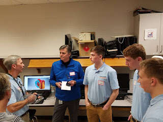
I soldered on the Arduino Nano to the circuit board. I also got the code uploaded onto the Nano and tested the circuit. It worked as expected and I’m hoping to connect it to the main leg to try and get readings. We had a meeting about integrating the hardware and software, and how the list of processes would work. I took notes on that. I also wrote a request to Kwik Trip for a donation so we can go to MIT in June.
 |
| Students deciding how they want the hardware to interact with the software. |
 |
| Alex troubleshooting the charging circuit. |
 |
| New spring mount next to the old push rod. We are testing to see which one works better. |
 |
| Before the spring is bent in a brake to get correct angle. |
 |
| After the spring is bent in the brake to get desired angle. |
 |
| The mount was cut out to accommodate the new spring linkage and then attached to the main gear. |
 |
| Rear view of the attached spring linkage. |


