Tuesday, October 30, 2018

Guest Speaker Mike Wettstein


Date:10.30.18
Location: Logan HS
Time: 9:20-10:05 AM
Students: All in 3rd hour DE class.
Goal: Discuss alternate methods to harvest energy from walking movement.
Mike Wettstein was our guest speaker today on the topic of alternate methods to harvest energy from motion. He brought in some industrial piezo devices which vary in price from $15 up to very expensive.
Piezo uses a wave form that is very sporadic. He explained the importance of using a full wave rectifier and why most charging systems for phones and other devices are called transformers when they are really a power supply and bridge rectifier. You need the rectifier because the AC wave from needs to be switched so it is positive and does not drop negative. A capacitor is used to smooth out the waveform. He suggested we use a charge controller to monitor the voltage from the rectifier.
A door bell system could also be used which uses a push button to move a rod through a coil. No gears are used and therefore no wear and tear. A linear solenoid used as a door opener could also be used. We would need to switch it to charge the magnet on the inside instead of the outside.
Piezoelectricity is the electric charge that accumulates in certain solid materials (such as crystals, certain ceramics, and biological matter such as bone, DNA and various proteins)[1] in response to applied mechanical stress.
https://en.wikipedia.org/wiki/Piezoelectricity

Power generation with shoe

Site to purchase Piezo disks

“In sole generator”

Piezo battery charging system in a shoe

Full Wave rectifiers

Linear solenoid actuator
https://www.electronics-tutorials.ws/io/io_6.html

Example of linear solenoid


Mike talking to the students on harvesting technologies.


Mike brought in some commercial piezo components for the students to look at.


Energy Management System for Prosthetic Limbs

Energy Management System for Prosthetic Limbs


Logan High School awarded a Lemelson-MIT InvenTeam grant in the amount of $9500 to create an Energy Management System for Prosthetic Limbs. The invention will harvest kinetic energy from human motion to generate and store electricity for prosthetic limbs. Logan High School is one of 15 high schools nationwide to be selected as an InvenTeam this year.

The Logan InvenTeam will design and build an improved charging and use management system to supply electricity to an electric vacuum pump in a lower leg prosthesis. This will greatly improve an amputee’s freedom by extending the time he/she can use the limb without being restricted to plugging it into a wall socket to recharge. The invention will have an energy harvesting module that converts the kinetic energy produced in a walking motion into sustainable energy using piezoelectric or electro mechanical technologies.

The Logan Lemelson-MIT InvenTeam
Back-(L-R)Alex, Seth, Tanner, Nathan, Thomas
Front-(L-R) Joel, Thaying, Paige, Caitlin, Austin


 “One of our goals is to provide an authentic engineering experience for students. However, in completing this project, they also have an opportunity to make a difference in peoples lives.” -Steve Johnston, Logan HS Technology & Engineering Department

Through the school 2018-19 school year, the Logan InvenTeam will develop its Energy Management System for Prosthetic Limbs. In June, the students will showcase a prototype of their invention at EurekaFest at MIT in Cambridge, Mass. EurekaFest, presented by the Lemelson-MIT Program, is a multi-day celebration designed to empower a legacy of inventors through activities that inspire youth, honor role models and encourage creativity and problem solving.

The Logan InvenTeam has partnered locally with Hanger Clinic and the Limb Lab of La Crosse and  5280 Prosthetics in Colorado. They will also work with local medical personnel and engineers who will guide the students through the development of their invention.  

Please consider donating to our project to help us defer the cost of travel and expenses to go MIT in June 2019 to present our invention at EurekaFest. This link will take you to our fundraising page:  https://lacrosseeducationfoundation.org/logan-invent/


Media links on the project:


Project Sponsors (Please let us know if you want to help sponsor our team):


Thursday, October 25, 2018

Work Night 10.25.18

Date: 10.25.18
Location: Logan HS
Time: 4:30-7:00 PM
Students: Dale, Thomas, Seth, Tanner, Avery and Paige
Goal: Look at math calculations on the efficiency of Piezo and electromechanical.

Mr. Foye was our guest speaker and had a number of spreadsheets to look at the differences in electrical output for piezo and electromechanical.

Some assumptions were made based on averages. We decided our target goal was 13.5  KJ for a battery recharge. We based this on 15,000 KJ per day total body energy consumption and 15 KJ would be used walking. We also assumed the average person uses their legs (movement) 2 hours per day.

Based on the data Piezo is not going to be a good choice for our solution. The output of the elements will be too low.

We then looked at electromechanical using motors to generate electricity and using gearing to improve the output. Students used multimeters to test different motor outputs with varying success. This proved to be more effective and we further discussed some solutions we could incorporate.

We will have to test the motors for K factor which is volts per RPM.

Sketch Idea #1


Sketch Idea #2

Students testing motor outputs to use as possible generators.


Tuesday, October 23, 2018

Hanger Clinic Tour

Date: 10.23.18
Location: Hanger Clinic, La Crosse, WI
Tour guides: Luke and Mike
Students: The entire team
Time: 9:20-10:45 AM


Questions for Hanger Clinic Staff
1. If we add a component that has spring force can you compensate in the design of the prosthesis? Yes.
2. Where can we play? In what spaces can we build/modify?
Higher on the Freedom foot is better (on the “C” part of the foot). We can build on both sides of the foot. Epoxy can be used and we can rough up the surface to do that if needed. We can build almost anywhere except where it would restrict the movement of the split toe or effect the placement of the foot.
3. What is off limits (don’t drill holes or modify)?
Can’t drill in the carbon fiber or even scratch it. We could drill an 1/8” hole in the aluminum tube on the lateral sides where tension and compression forces would be reduced, but he said we would have to ask the engineer for sure. We can use the split in the toe to run wires through but warned the carbon fiber edge is sharp so the wire would have to be protected. Luke recommended some clamping mechanism to hold on our components as opposed to drilling.
4. Is there a space we can harvest vertical or linear movement?
Luke did not have any more insights on this other than what we have already talked about. He did mention the spring force rebound as the foot rolls off the toe.
5. How much motion should we expect in a heel deflection when it strikes the ground? He felt the average would be between 0 and ½”. The heel should never bottom out. If it does it is a design flaw and it could crack the carbon fiber. He also felt the majority of “feet” are like the Freedom foot we have to work with. Some will vary in height, but the one we have for testing is representative for the average. The heel is the damper, the forefoot is the storage and energy release.
6. Any rotational movement when the prosthesis strikes the ground? Yes, the knee and ankle can rotate a little. When people run they run on the outside of the foot. When they walk the walk on the inside of the foot. They fit the foot based on the average % of running and walking the patient will do. This is done on a treadmill to finalize the fit.
7. Where can we drill holes? Basically nowhere unless we can drill in the tube.
8. Can the inside of the tube be used?
Yes it can. It is open for us to use same as the outside of the tube. Luke did not seem to be concerned about something sticking out from the tube.
9. What is the weight budget for the foot? How much weight can we add before it is too much?
Luke said it would be no problem adding a reasonable amount of weight. People have Freedom Feet that weigh 3 times what ours does and they have no problem with it.
10. What is the range of motion when someone steps? What does it look like?
Heel strike first then roll to toe and spring off to the next step. It is important for the toe to have spring to help move the limb toward the next cycle.

Other notes:

If something breaks on the Freedom foot, they have to send it back to the manufacturer who determine if it is a design flaw or they made a mistake fitting the prosthesis.
The rubber feet are molded to fit over the freedom foot and they have a molded in heel inside to give additional lift.
Some people do not use the rubber feet, they glue on tire rubber to the bottom of the foot and use that during the winter.
There is a 3.5 year warrantee on the Freedom Foot.
A mid length amputation is the easiest to work with. That is defined as 6” below the knee on an average person.
Average toe deflection on a Freedom foot is up to ½”.
The mechanical knee is designed with a geometrical locking mechanism to allow the natural movement of the knee forward before starting to initiate the bend.
The shorter the amputation, the more the prosthetic fitter has to work with.
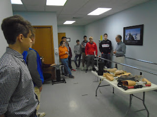
Students at Hanger Clinic 

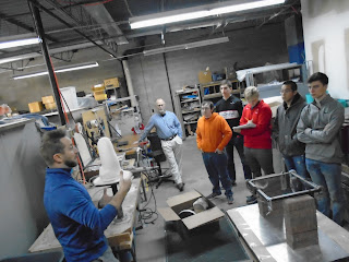
Students seeing how a prosthetic limb is made.


Email from Clint at 5280 regarding SmartPuck Components:

Awesome!  Let us know how we can help.  

The fixture we sent will allow the students to see how the vacuum affects the limb.  If the liner top is reflected over the top edge of the socket (with the bulk of the liner in the socket). You can see how the liners is drawn to the walls of the socket when the vacuum pump is activated.  It takes a while due to the amount of air in the socket.  

We can send other prosthetic components if you need them (feet etc).

Good luck,


Monday, October 22, 2018

5280 Smart Puck Components Come In

5280 Smart Puck Components Come In
Date: 10.22.18

Good News! Clint at 5280 Prosthetics sent out the components you see pictured below and we received them today. It is all the electronics that we need to test our charging system on a real SmartPuck. Special thanks to Clint and the 5280 staff for their support and advise as we continue to move forward.


Circuit boards, vacuum pumps, batteries, charger and SmartPuck with socket.

Saturday, October 20, 2018

Flywheel Basics


Date: 10.20.18
Location: Logan HS
Time: 9:00-11:00 AM

We may want to look into this. Flywheel generators or alternators. What we
are trying to do is capture the vertical motion when the heel flexes on a
prosthesis and convert it into electricity.

Kinetic energy can be described as "energy of motion," in this case the
motion of a spinning mass, called a rotor.  The rotor spins in a nearly
frictionless enclosure.  If we can use the flexing of the prosthesis to
power a small flywheel, the inertia allows the rotor to continue spinning
and the resulting kinetic energy is converted to electricity.

Video on how a flywheel generator works (we could make one but much smaller
than the one in this video):
https://www.youtube.com/watch?v=-8baGs5bbY0


I know this looks old (1970's) but they sold toy cars called SST Racers that
had a flywheel in them. You pull the strip and the car would be powered by
the flywheel.
https://www.youtube.com/watch?v=_NxQf-aeDWk


This is a video of a flywheel generator using a recording head out of an old
VHS player. Don't worry about the scale right now. We can make it smaller by
miniaturizing the components. Some of our old Mini DV cameras may have a
recording head in them.
https://www.youtube.com/watch?v=OaAYt8NJsvE

Friday, October 19, 2018

Workday 10.19.18

Workday
Date: 10.19.18
Location: Logan HS
Time: 1 hour
Students: Paige and Alex


Sketch of linear Altinator
Model of leg motion tester

Monday, October 15, 2018

Energy Management System for Prosthetic Limb Work Day 10.15.18

Energy Management System for Prosthetic Limb Work Day

Date: 10.15.18
Time: 1:00 – 3:30 PM
Location: Logan HS
Goal: Research piezo and electromechanical solutions and begin to look at ordering components to experiment with.
Students: Alex, Seth, Austin and Thomas

We talked to a tech from Piezo.com. It was a very enlightening conversation. Here is a summary of the conversation:
1. He recommended buying the cheap piezo speaker elements (we have about 12 of them now) and experiment bending them back and forth to see what we can get out of them.
2. Use JB Weld or an epoxy to attach them to a 1/16" or 1/8" metal plate that can bend or use springs in the arch of the foot to get it to flex. (Not sure how that would be mounted to the artificial limb. We would have to drill small holes to attach.)
3. Do not wire them in parallel (even though that would seem sensible). Wire them in series with each one having a separate rectifier or diode. Using a full bridge rectifier would be the best option here. One rectifier is enough as everything can tie into that.
4. The output voltage is proportional to the number of times you bend the element.
5. If you go to the link below you will find a recommendation he made for a harvester that is somewhat more developed and easier to mount. The kids would have to be careful with this as it does not bend like a playing card and is designed to be mounted to a surface. He felt the wear and tear under the foot would be ok though.
http://piezo.com/prodproto4EHkit.html
6. He also said, “Don’t go off of the output specs noted on the web page.” These can vary.
7. The kit costs $660 which is within our budget. If we needed just the bender and not the circuit (because we can design our own circuit) that price is cut in half.
Alex-Worked on a plate for connecting the piezo components. Learned that the flex of the foot can be used as a power generation point for the piezo. The Piezo element creates a high but short jump in voltage (of 5-10 volts), as discovered by using the oscilloscope. The element jumps between positive and negative voltage when flexed. It was discovered that the voltage reached the highest point when the lever on the element was higher (having it’s own wires supporting it). The element also jumps from negative voltage to positive voltage first depending on what direction it is flexed. Piezo elements should also be wired in series and NOT parallel to generate power if using two on the same circuit.

Seth-Worked on electromechanical component that would fit in the shoe. He also found a magnet and went to Menards with Thomas and Austin to look for materials (PVC pipe .4” inside diameter and unsheathed wire)
Thomas and Austin worked on software drawing for lower leg tube.

This was a research meeting to continue learning about the hardware options for our project. Alex Magnuson continued to work on looking into piezo hardware.
The electromechanical team including Thomas Kujak and Seth Peterson worked on design options. Thomas was working on creating a casing to hold the electronic components and Seth tried to find the magnets that would be inside of the casing. They then went to Menards and continued to search for parts.


Austin Research Notes:

I did some research on the Raspberry Pi Zero W and found out that it would require a digital to analog converter in order to measure voltage as the Zero W does not have any analog pins in it. It would take around 3.3 to 5v in order to power the chip(MCP3208) alone in order to do the conversion. We would need to do some testing to see if it would draw too much power or try to find an alternative. An idea would be to cut out a circuit board to put the chip into and use the board to supply power and receive the inputs via the Zero W. This would also add more size to the system and mounting on/in the leg would be more difficult. Some testing and more research would be needed to find out the best solution for the voltage monitor.


Alex checking piezo outputs with an o-scope.

Students working on the problem.

Thursday, October 11, 2018

Work Night 10.11.18

Work Night 10.11.18 

DATE: October 11th 2018
TIME: 4:30 - 7:00 (2.5 hours)
Location: Logan HS
People Who Attended:
- Avery Schams
- Alex Magnuson
- Seth Peterson
- Tanner Boge
- Dale Lawrence
- Caitlin
- Paige Treakle

Research Meeting for Prosthetic Limb - Lemelson MIT InvenTeam

This was a research meeting to begin our research on solutions for creating a prosthetic leg for a below the knee amputee that creates its own energy and is controlled by a phone application. Alex Magnuson and Avery Schams delved into research on piezo hardware would help us create an self-sustaining energy source . It has crystals in the device that are vibrated. When pressure is put on the device more energy is produced. Seth Peterson and Tanner Boge reviewed the background information on the project and looked into linear alternators. Dale Lawrence also did research on linear alternators. Caitlin looked into requirements for creating google play and apple store applications. The ultimate goal is looking into which  application approach is better or if a hybrid should be created. The application fees, application maintenance, and the bluetooth capabilities were also recorded. Paige Treakle looked into Lemelson MIT InvenTeam communication requirements, social media platforms that would promote the team, and overviewed the team member’s process.

Wednesday, October 10, 2018

Dr. Esher talks to the students on amputations

October 10th 2018
Date: 9:40 - 11:05
Notes taken by: Paige Treakle
Location: Logan HS


Dr. Escher Amputee Lecture:

1) Dr. does everything possible before coming to the conclusion that the limb needs to be amputated.
a) For legs it is either Above the Knee (AK) or Below the Knee (BK)
b) Brings up amputation over many visits to allow patient to have time to process the situation and make a decision
i) People react differently
(1) It is like losing a loved one for some
(2) Others just want it done and over with
2) The limb is cut off typically because blood isn’t flowing to the limb properly
a) Major part of limb is cut off using a saw
i)
ii) Has a chain like saw in middle with handles on sides
b) They leave a small portion of the tibia bone (during BA amputations) and round the edges using a file (so that the bone fragment wont cut through the skin when pressure is put on the bone).
c) They also leave a flap of calf remaining
i) Part skin
ii) Part fat
iii) Part muscle
d) The calf-flap is then sewn to cover the wound and the stitches are done on the front part of the leg
i) This makes the weakest part of the stump have the least pressure
ii) The bottom of the stump does not need to heal because it is part of the calf
iii) As the stitches are healing the amputee cannot use a prosthetic because it can wear on the incision and cause the stitches to break
iv) As the wound heals the skin from the calf flap and the original thigh skin will form together
(1) The stitches only hold the wound together, the body will heal the wound itself

Dr. Esher talking to member of the Logan InvenTeam

3) This procedure can take weeks to heal
4) Remember this prosthetic leg and stump is holding the weight of your body!
5) The prosthetic can be made from plexiglass, aluminum, ect
a) The stump will need a ‘sock’ so it is not skin on prosthetic


Tuesday, October 9, 2018

Work Night 10.9.18

Work Night
Date: 10.9.18
Location: Logan HS
Time: 4:30-7:00
Students: Avery, Caitlin, Dale, Alex and Paige.

The goal tonight was to research the problem and begin to collect some data on heel strikes (the pace of someone walking) to get an idea on what is considered an average pace.


Student testing data on walking.


Students working on background research

Friday, October 5, 2018

Introductory Experiments with Piezo Components

Introductory Experiments with Piezo Components
Date: 10.5.18
Location: Logan HS
Time: 1 hour
Students: Alex and Paige

Students researched some preliminary wiring configurations for piezo components. A circuit was created and the components were tested based on voltage output just to get a feel for what kind of technology we are working with. We purchased 12 piezo components for $6 on Amazon.

Alex wiring a piezo circuit together.

Alex and Paige beginning to test the component for voltage output.