Friday, April 26, 2019

Work Night 4.25.19

Work Night

Date:4.25.19
Location: Logan HS
Time: 5:15-7:15 PM
Students: Avery, Tanner, Seth, Alex, Paige, Thomas and Austin
Goal: Test new generator configuration under load.

We have been having more difficulties with our limb tester. We blew a 12.5 microFarad capacitor and need to order a new one. The capacitor is used in motor startup for the tester. All testing stopped until we got it back up and working. Also, some of the bearing and moving parts needed to be greased and refitted with normal wear and tear occurring from use over the course of the year.

Once we fixed the tester we were able to start collecting new data on our 18 V generators and new 12 V generators to see which ones would give us the highest current output. We finished the night by getting most of the data collected and still have to try a mixed configuration (one 18 V and one 12 V generator) wired together to see how that looks. Once all the data is collected we can make a decision on which configuration is the most efficient for us. Keep in mind that our generators are really stock DC motors that we are re-purposing for this application.

Software has made some nice advances and our wireless (Bluetooth) connection is now configured for 2 voltage inputs and one enable (on/off) switch. Bench testing was positive on the setup so we will mount the new board this week and then test it next week with the limb tester and full charging circuit. If that is function, we will have made hit all our targeted goals.

We are still progressing on the patent application. Work is slow as it is new for us. Our industry contacts  have been very helpful here as some of them are patent holders and are very willing to help us with the terminology and process.


New 12 V motors that came in from India. Notice the packaging.

The new motors came with this envelope indicating they were the first motors Portescape had made of this variety. They are still stock motors, but apparently they were the first run.

Motors after we added the pinion gear and extension wiring and shielding. Notice the manufacturing label on them indicating 001 and 002.

Paige and Austin working on the wireless connection circuit board amid the clutter of pizza and treats.

Tanner, Seth and Avery working on the design for the production concept.

Wave form output for our 18 V motors through the charging system. The yellow line indicates the capacitor charging and the blue line indicates the duration of the constant voltage supplied.

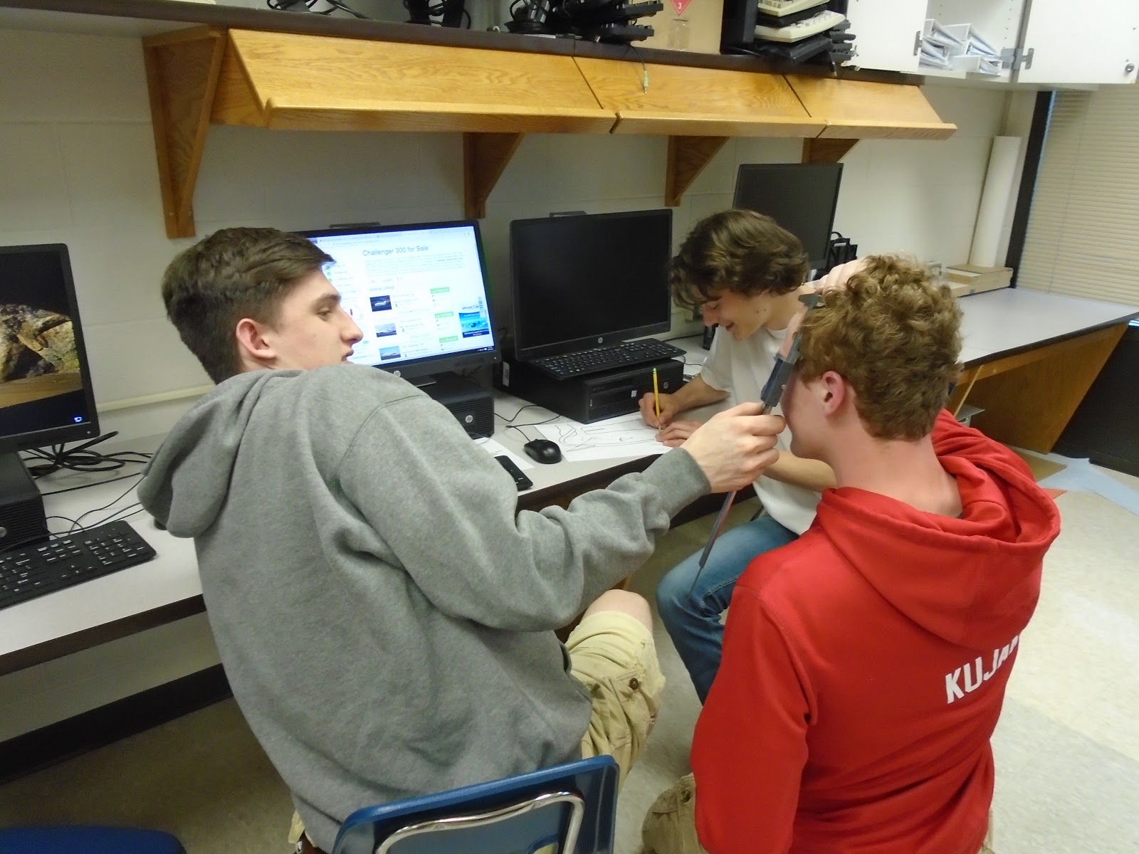
Seth measuring Thomas' forehead...not sure what that has to do with the project, but it looks like they are having fun.

Wave form output with our new 12 V motor output through our charging system. The blue line indicates some transient activity is happening toward the end of the wave form. 


Thursday, April 11, 2019

Work Night 4.11.19

Work Night 

Date: 4.11.19
Location: Logan HS
Time: 5:15-7:15 PM
Students: Tanner, Seth, Alex, Paige, Austin, Thaying, Avery and Thomas.
Goal: Test the new charging circuit for functionality.

We needed to test the updated charging circuit and had a problem with one generator outputing the correct voltage. It seemed one of the generators was not functioning properly. When we cycled the tester, we were only seeing one output on the oscope. We felt it was a mechanical malfunction, but after some testing we determined both generators were functioning in the new mount we 3D printed with the (gray) supports we added for additional strength. It had to be wiring or some other electrical issue which we will have to trace down next week.

The new 12 V motors will hopefully be in next week with the 8:1 gearhead. We are hoping this adds to the durability of the generator system. The current motors we are using have a plastic gearhead.

Team members also worked on the patent information. We feel something that makes our system unique is the fact that our design does not change need to change foot of the artificial limb by adding motors or gears as in some other designs. This keeps the cost low and increases simplicity . It will work on any Freedom foot which we were told is the most popular prosthetic foot. The only thing that may need to be modified is re-3D print the heel adapter for the size of the heel. Which would cost pennies.

We also spent some time redesigning the charging port that goes in the vacuum pump. The current one is proprietary and is big and bulky. We needed to design a more streamlined one that would not be so bulky. Students found a way to modify the current adapter by doing some cutting and drilling some new openings and then using epoxy...at least that is the current plan.

UPDATE 4.15.19
We worked on troubleshooting the motor and electronics to try to trace down the fault in the circuit that was giving us zero output from one of our generators. It turns out one of the green terminal blocks was mislabeled and therefore we wired one of the generators in wrong. This was the reason we showed no output from that generator on the oscope. When we corrected it you can see the output was back to what we expected. In fact, it worked exceptionally well. The output was giving us the voltages we needed and was charging the caps and we demonstrated that by lighting up some LED's to show how the system worked. Using our safe (low charge) setting we were able to light the LED's in about 15 sec.
The oscope shows the output from our generators to our storage system.  This is important because it shows
the success of our charging system. Now we just have to tweak the software.


New supports for the motors in gray.


Thomas and Alex working on the LED array.

Seth, Tanner and Avery working on redesigning the charging adapter for the vacuum pump.

Friday, April 5, 2019

Work Night 4.4.19

Work Night
Date: 4.4.19
Time: 5:15-7:15 PM
Location: Logan HS
Goal: Complete further testing on the charging system and begin to write the patent.
Student: Alex, Thomas, Austin, Paige, Seth, Avery, Caitlin, Tanner and Paige.

We broke another gear on one of the generators on Monday so we repaired it and tested it again and it seemed to work. We have isolated the problem and need to support the gear housing better from the heel strike impact force. We are working with stock motors and plastic gears. Some of this is to be expected. A production model would incorporate metal gears and a larger diameter motor shaft. Our current one is 22 mm.

We also did some testing with a new 10 lbs spring attached to gear which resulted in about ⅓ of the voltage of previous spring so out output was lower. We will need to go back to our 20 lbs spring to increase our voltage output. We also had something go wrong with the charging circuit and our positive cap doesn’t charge properly and doesn’t discharge properly. We double checked labeling and connections on system diagrams and checked connectivity and solder joints

Tanner, Caitlin, Avery, and Austin worked on the patent. They are working on defining our abstract definition and also added more information about the software to the summary of our patent application.

Caitlin also worked on making some additions to the layout of the app (added more clear and visible constraints to the text).

Friday- 4.5.19  Update: In testing the charging circuit we found that some solder joints needed to be corrected, but most importantly one of the super capacitors appears to be damaged. Otherwise circuit works perfectly! This was a risk area as we are operating outside the specs for surge voltage, and it is unclear if the technology will support the high currents. We can modify the circuit to reduce stress but retain the full capacity. As an alternate, we could have a full electrolytic cap bank, but it would be physically larger.


Alex and Thomas troubleshooting some electronics.

Students working on the patent application.

20 lbs spring on the left and 10 lbs spring on right.

Seth adding support structure for the generator mount.